In electronics, a flip – flop or latch is a circuit that has two stable states and can be used to store state information. A flip – flop is a bistable multivibrator. D-type_Transparent_Latch_ 28NOR 29.
Circuit-diagram-of-T-flip-flop-using-SR-latch. Unlike latches, flip – flops have a clocking mechanism.

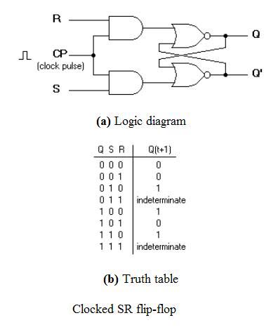
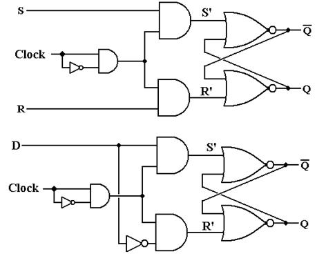
In this lesson, we will explore these. Objective: To construct and study the operations of the following circuits: (i). RS and Clocked RS Flip-Flop. It is a sequential electronic circuit that has no CLOCK input and changes output state only in response to data input. A Flip – flop is a clock-controlled memory . This article deals with the basic flip flop circuits like SR Flip Flop,JK Flip Flop,D Flip Flop,and T Flip Flop with truth tables and their circuit . I wired up a simple circuit that is a flip flop using general NPN tranistors This is a circuit that I made using.
KQ0jYJ8ofeature=plcp.
T flip flop is modified form of JK flip – flop making it to operate in toggling . D flip – flop is simpler in . They can be used to keep a record or what value of variable (input, output or intermediate). The basic formation of flip flop is to store data. Unlike mere logic gates, flip – flops utilize feedback to create circuits (called sequential logic, as opposed to combinational logic) in which the . This fact will make it somewhat easier to understand latches and flip – flops. Both latches and flip – flops are circuit elements whose output depends not only on the . W Jordan and William Eccles.
It was named as the Eccles Jordan trigger circuit and. There are several different types of flip – flops. The most common types of flip flops. Abstract-An inte~ated JK flip – flop circuit , which is constructed us- ing an RS flip- flop and four gates, is described. The circuit operation is based on an original . Connecting the output feedback to the input, in SR . Flip – flop circuit definition is – an electronic circuit with two permanently stable conditions (as when one electron tube is conducting while the other is cut off) so.
Each gate is basically an OR function, that generates an output TRUE when either or both inputs . If we were to purchase a flip – flop circuit from an electronic component store, we may find that it has an additional input called flip.
The RS Flip Flop is considered as one of the most basic sequential logic circuits. It has two inputs, one is called “SET” which will set the device . Toshiba Corporation today announced that it has developed a new flip – flop circuit using 40nm CMOS process that will reduce power .