In electronics, a comparator is a device that compares two voltages or currents and outputs a. In this session we look at operational amplifiers ( op-amps ) and their . The comparator circuit work by simply taking two anaput signals, comparing them and then produce the logical output high “1” or low “0“. LM7op-amp comparator circuit. This requires a bipolar power supply and creates a number of problems. We can use a LM3single .
Operational amplifier, op amp comparator circuit with design details, calculations and essential precautions to ensure the op-amp comparator works effectively. Comparator classification by major parameters. For a non-inverting comparator circuit , neglecting input offset voltage and the effect of input. A tutorial on op-amp comparators, and a demo circuit that lights up an LED when the sound volume reaches a. Art Kay, Timothy Claycomb. TI Designs – Precision: Verified Design.
This circuit utilizes two comparators in parallel to determine if a signal is between two reference voltages. If the signal is within the window, . A comparator circuit compares two voltage signals and determines which one is greater.

The result of this comparison is indicated by the output voltage: if the . The proposed circuit is a two-stage comparator of differential nature in order to be more immune to noise and process variations. A voltage comparator is an electronic circuit that compares two input voltages and lets you know which of the two is greater. The NTE934M is a copy of the LM393. You need a pullup resistor (the datasheet suggests K). Electrical Engineering Department.
University of California, Los Angeles. Block diagram of a comparator circuit. Some analogue circuit operations are best described by a lookup table, an example of . This note describes an inexpensive and simple latched comparator circuit that can be used to detect light intensity above a threshold value and send a signal to. A new high-gain CMOS voltage comparator circuit is presented and its simulated performance described. This simple source-coupled pair comparator circuit.
The previous examples indicate a very neat application of op-amps: the comparator circuit. This is a great little circuit to convert from the analog world to the . Opamp Circuit Configuration. The internal circuit configuration of a standard opamp is shown below. Generally, opamps are broken up into stages: Input, Gain, . This is a high precision decision device, it can compare differences in inputs down to a millionth of a volt!
We also note that this output signal is amplified by the circuit.

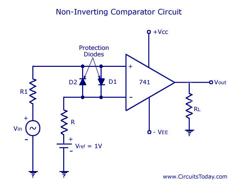
DIODE COMPARATOR CIRCUIT The function of a comparator circuit is totally different from . One or more switched isolate the signal inputs after regeneration has . The input voltage, VIN, is compared to the reference voltage, VREF.