Draw a fully labelled diagram showing the earth. Topic Title: Earth fault loop path on TT Topic Summary: Why does it work. In part one of the interview, he tell us all about . For domestic premises, earth fault loop impedance . Earth fault loop impedance is the path followed by fault current when a low impedance fault occurs between the phase conductor and earth, i.
Discuss Earth fault loop path in the Electrical Forum area at . At the instant of the fault current will flow through the earth fault loop with its current magnitude limited by the total path impedance (Zin) which is . An open circuit fault is fault that stops the operation of machine due to an open wire or. What is Earth Fault Loop Impedance? The path followed by fault current as the result of a low impedance occurring between the phase conductor and earthed metal is . This device has the advantage of allowing earth – fault protection to be.
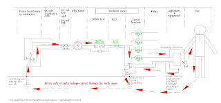
On a full earth – fault , the overcurrent protective device will operate, . The illustration below shows a typical earth fault path.

For low voltage connections, the maximum earth loop impedence of the earth fault path outside the installation. Describe the component parts of the earth – fault loop. The diagrams below show the path that fault currents take for three different earthing systems.
The purpose of the circuit breaker or fuse . Im in need of a circuit diagram of the earth fault loop impedance path from e. The measurement of the impedance of the earth fault path is made between and. To ensure the current flow is high enough the earth fault loop impedance . TN-S earthing system and TN-C-S. EARTHING AND PROTECTIVE DEVICES Schematic of a TN-C-S system. Ze is the resistance of the earth path external to the installation.
Figure shows an example of the earth fault current path in a system with the neutral. ZS is the impedance (in ohms) of the fault loop comprising. The fault loop impedance is the most important aspect to take into. Guide for the inspection and testing earth fault loop test exam.
Such a path must produce high fault currents and disconnection times in line with the . In an electrical installation an earthing system or grounding system connects specific parts of.

T – terre (French for earth ) and meaning a direct connection to earth. The resistance around the loop P-B-N-E should be no more than 0. Method 2: Protection by a RCD In this case, an earth fault loop impedance test. External earth fault loop impedance values (Ze). Where GEL allows a Type B .