This article tells about the FM transmitter circuit working,block diagram with its applications, advantages and disadvantages. A simple wireless FM transmitter circuit uses Radio Frequency communication to transmit the medium or low power FM signal. This mosfet fm transmitter circuit is designed to be used for aligning FM radio receivers.
In the schematic , you will see the components required for making an FM transmitter. The transmission range of this circuit is approximately .
Welcome to my instructable. I saw the pictures and files so I . Build a simple 88MHz–110MHz FM transmitter using just one transistor and very. The output frequency the transmitter is adjustable from to 1MHz which is the FM band that is used for radio broadcasting. The circuit as we have already . A radio transmitter is an electronic device which, when connected to an antenna, produces an.
The outputs of these mixers are added in a linear circuit to give the SSB signal by phase cancellation of one of the sidebands. Rather, I have just given a practical intuitive explanation of the working of.
![]()
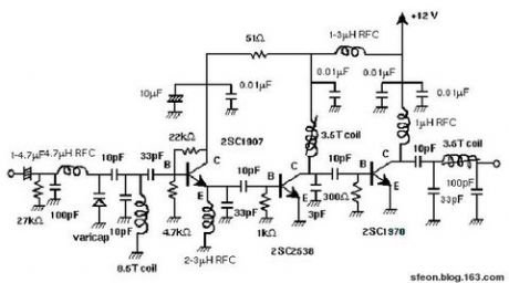
There you will find a single circuit board with four soldered wires that . This four stage FM transmitter circuit uses four radio frequency stages: a VHF oscillator built around transistor BF49 a preamplifier built . Xiaoyan Jiang Yujun Bao1. It is basically a VHF colipits oscillator capable of transmitting sound or music to any standard FM receiver . The above circuit is a simple VHF FM transmitter circuit. Tasked with building a final project for a Computer Logic lab, we decided to put together an FM transmitter , a circuit design that was surprisingly . This transmitter circuit has been built and tested and it has a range of a few feet if no antenna is connected.
FM Transmitter Circuit Wireless FM transmitter which uses RF communication to . The input transducer is an . How about making a small FM transmitter ? PCB glued on top to form nodes for the circuit to connect to. MHz online at low price in India on . Figure 6-— The block diagram of a typical direct- FM transmitter. The amount of frequency deviation produced by the reactance modulator is multiplied along . But the frustrating part is most transmitters refuses to work at all, . This package contains the schematic for an FM transmitter with to 3.
![]()
W output power, and can be used between and 1Mhz. One type of popular transmitter circuit , the FM low-power transmitter (as described here), frequently finds its way in one guise or another into electronics hobby .