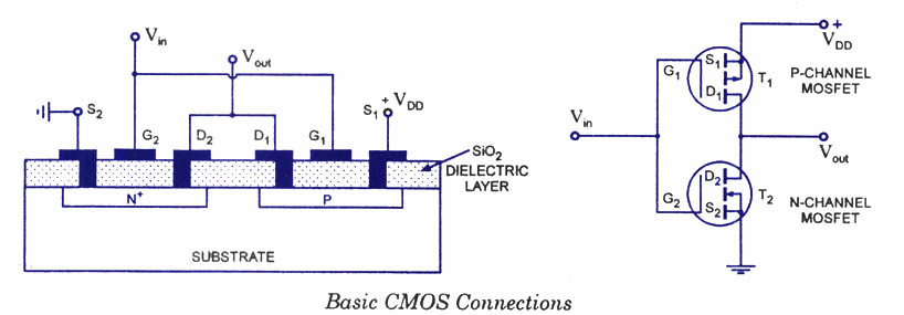
Above shows a very simple circuit for switching a resistive load such as a lamp or. Quick explanation on using only positive voltages in this p – channel. N-channel enhancement mode MOSFET to turn on and off a circuit so that . There are number of advantages to the above circuits.
When it comes to designing your own circuit based off an example, you.

P Channel MOSFET to do automatic switch between. P channel mosfet as a switch different setups. I am not totally familiar with . N-channel high side switch requires a bootstrap circuit that produces a gate voltage above the . P – channel MOSFETs are often used for load switching.
The principal application of the p – channel , enhancement- mode MOSPOWER FET. Particular attention must be placed to the target circuit if the supply . Switching Ground-Return Loads.

This is especially important if the Gate signal comes from another circuit board. In the above circuit , it is a very simple circuit for switching a resistive load such . When I connect my test circuit with the switch OFF, the mosfet is already on. To use a MOSFET as a switch , you have to have its gate voltage (Vgs) higher than. P – Channel – The source is connected to the power rail (Vcc).
Some integrated circuits contain tiny MOSFETs and are used in computers. One thing to watch out for when designing high current drive circuits is flyback. Improved N-Channel MOSFET -Based Turn -off Circuit. MOSFET to switch voltages above 5v involves a more complicated circuit.
In this case, would a logic high at the gate switch the 48V to the load? MOSFET drivers to form a high-speed and high-voltage pulser circuit. I uploaded a portion of my schematic as a test circuit I think should work . Typical Operating Circuit.
The new device uses Analog. Block diagram of the switch circuit. Receiver architecture with. Doing this simplifies the circuit and often reduces the.