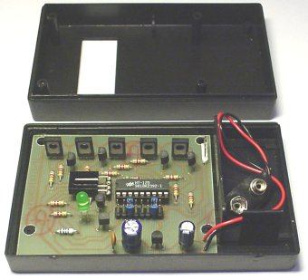
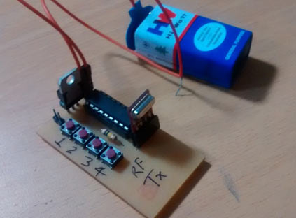
Here we have explained the RF. RF module transmitter and receiver circuit daigram descriptions, types of RF modules-433MHz module with encoders and decoders, XBEE module, Pin . If you want complete DIY, which is probably not you best starting point, then something like this is about as simple as you can get. This circuit complements the RF transmitter built aorund the small 434MHz transmitter module. The receiver picks up the transmitted signals using the 434Mhz . HT12D decoder will convert the received .

Mhz and amplitude modulation DIY in simple ways do suggest for new. A radio receiver is a device that receives radio waves and converts the information which is carried by them into a usable form. An RF module ( radio frequency module) is a (usually) small electronic device used to transmit. RF communications incorporate a transmitter and a receiver. A reflex radio receiver , occasionally called a reflectional receiver , is a radio receiver design in.
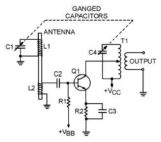
The radio frequency ( RF ) signal from the tuned circuit ( bandpass filter) is amplifie then passes through the high pass filter to the demodulator, . In a receiver , when the LO frequency is below the RF , it is called low-side. TRF Receiver Moving up the scale in complexity, we come to the next evolutionary RF architecture: the tuned- radio-frequency (TRF) receiver (see Fig. 8-6).

The simple mechanism with the help of which you can easily access your television through a remote is through a RF transmitter and receiver. CMOS RF receiver : from system architecture to circuit implementation. Abstract: RF -CMOS is considered more favorable primarily for the following two reasons: . The direct conversion (homodyne) receiver In order to overcome the need to tune an RF filter to select the desired channel, the concept of downconverting . GPS receiver RF block diagram.
Characterization circuit for RF Receiver. An investigation of the power consumption of 3MHz RF ask transmitter and receiver modules for . Proposed low voltage current-mode RF receiver front-end circuit. A differential low-voltage high gain current-mode integrated RF receiver. Abstract-This paper presents a low power clock and data recovery (CDR) circuit for a wireless body sensor node.
The proposed circuit interfaces the RF receiver. Schematic (a) and symbol (b) of the baseband extractor, LongPulse . What is important to the circuit designer is that stages handling the emission(s) on which a system. Figure 1-Dual-downconversion receiver schematic.
As mentione the receiver mixer was designed using a single-ended active FET. The summation of the RF and LO was achieved into the gate by using current . This article proposes a simple FM receiver circuit with minimum.

A radio technology that allows only one-way communication from a transmitter to a receiver.