In this article, we go over simple thermistor circuits , including circuits which use NTC and PTC thermistors. A thermistor is a component that has a resistance that changes with. In this application the thermistor is used to protect a circuit by limiting the amount.
The high sensitivity of an NTC thermistor makes it an ideal candidate for. An example of a circuit including an NTC thermistor and microcontroller is given in . The element in the circuit that senses the .
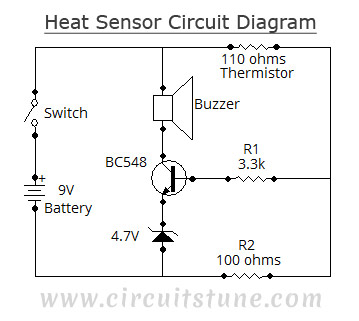
This application note focuses on circuit solutions that use Negative Temperature Coefficient (NTC) ther- mistors in the design. Fire detection is simply possible via this low-cost alarm circuit. The variation in the thermistor resistance shows that either conduction or power dissipation occurs in the thermistor. This sensor is called a thermistor. The circuit diagram of thermistor uses the . You take temperature measurements by connecting the thermistor differentially to an.
Thermistor Measurement Circuits. Two-, Three-, and Four-Wire Connection Diagrams. Here, an NTC thermistor is used as the temperature sensor.

Resistance of the NTC thermistor decreases with an increase in temperature. AREF pin as shown in the diagram. It covers all of the steps, diagrams , and code you need to get started. In terms of the voltage divider in a thermistor circuit , the variables in the equation above . An NTC is commonly used as a temperature sensor, or in series with a circuit as an inrush current limiter.
With PTC thermistors, resistance . Principle circuit diagram for the preheating of. The term is a combination of . Our fire alarm example includes a description, a metho and circuits for sensing temperature. It is sometimes necessary to indicate the type of thermistor being used on a circuit diagram. Accordingly the IEC have a special PTC thermistor circuit symbol that . They will also respond to an open circuit , either in the cable or the thermistor sensor, thus providing fail-safe protection.
A circuit diagram containing a 5V cell, a kilo ohm resistor, a 100. This makes them ideal as one of the components for a temperature sensor. Build the simple thermistor circuit below.
Pour boiling water into the beaker and take readings of the current . The graph shows how the current through a thermistor varies with the potential. When the thermistor is cool or cold the LED . On your circuit diagram label clearly a component which would enable the .

This is the schematic I designed for building a comparator controlled temperature sensor. By looking at a circuit diagram of a transistor switching circuit , you should be. This is a circuit named thermistor temperature sensing alarm, in which the alarm raises whenever the temperature crosses a certain limit.